All available Conventional Datas are collected from the Plant Resources and documented before the start of site set up for 3D Laser Scanning.
This includes Plant layout drawings, Equipment list, and any other relevant data which would provide additional help during 3D modeling after cloud processing.
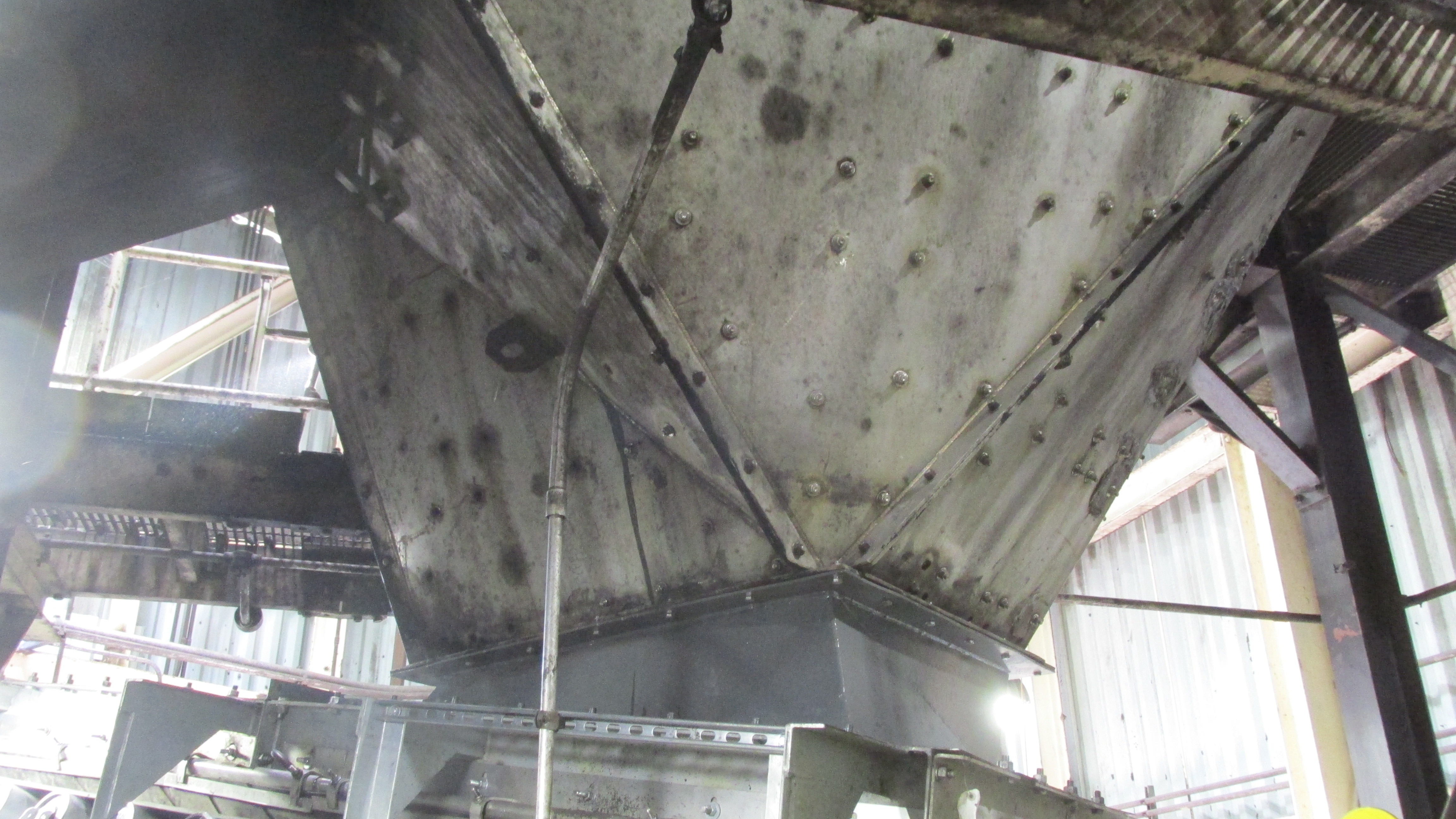
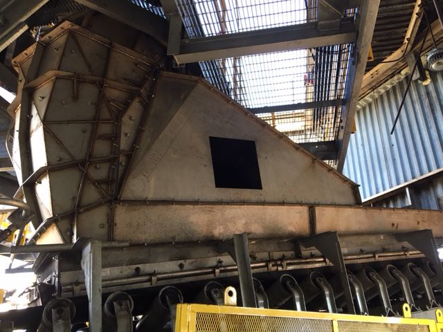
Old Chute
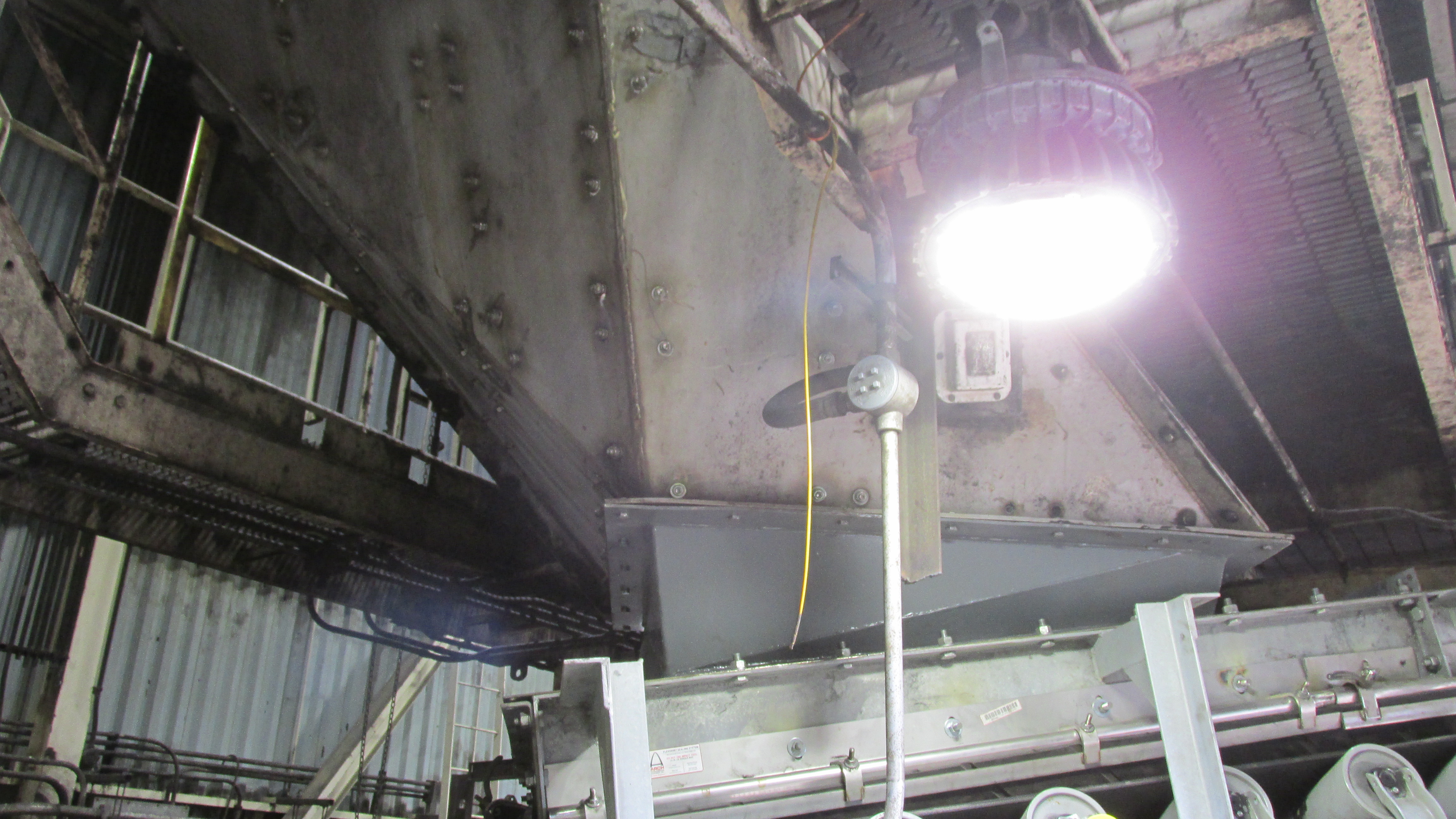
Old Chute had dust problem and leaks and material flow was off center.
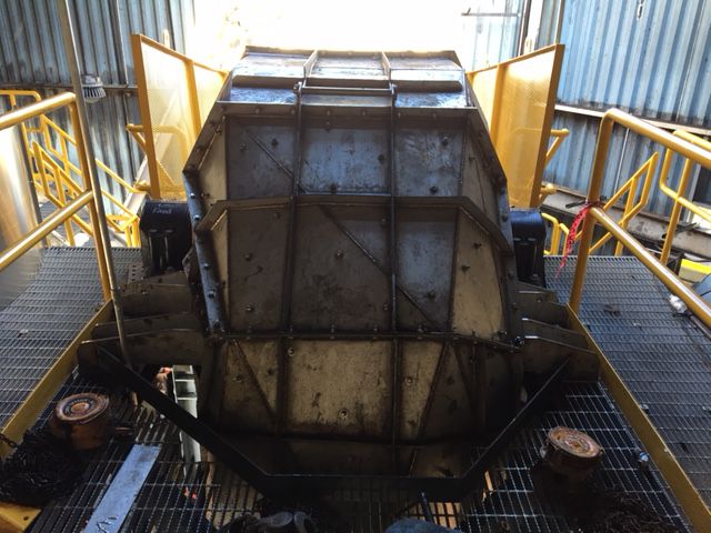
Old Chute - Alternate View
Once the Site Preparation and procedure is planned, the 3D scnning will be carried out followed by post processing. The Cloud Points after registraion is brought in to 3D modeling software and cleaned up.
The 3D Design activities starts at this juncture. The Engineer can Analyze the data and implement upgrades after the 3D models takes final shape.
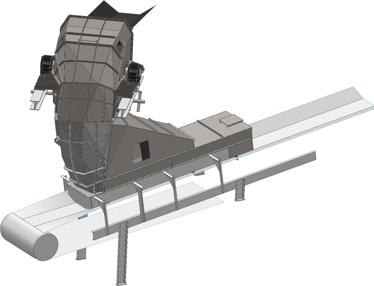
Generation of 3D Models and Drawings from Scanned Data
The scanned 3D model on the Right shows the old chute arrangement, which will be used for New Chute Geometry for correct fit up and for checking interference when final 3D Chute Model is generated.
3D models are modified for upgrades and necessary Drawings are generated for Data Storage for later retrieval or for Manufacturing Drawings for plant upgrade.
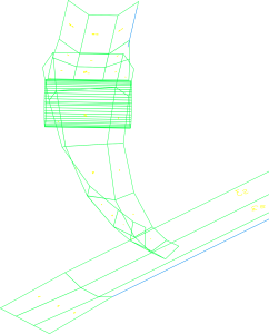
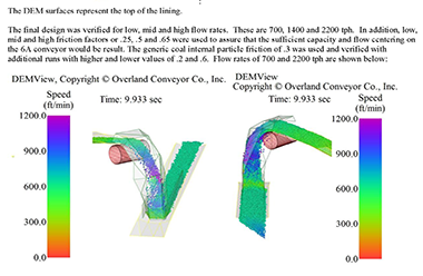
DEM 3D Surface Model
3D Surface Model was generated for DEM (Discrete Element Modeling) Analysis
DEM Analysis was carried out and acceptable flow Recorded
Engineered Flow Control Chute Model was generated from DEM Model and checked with existing Geometry for exact fit up.
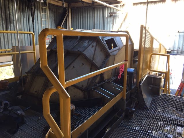
Below:
Views of New Chute Installed and Tested for Designed performance.
Professional Material Handling Solutions. Highly experienced & equipped personnel